
How ADI and NVIDIA Extended cuVSLAM with Wheel Encoders, IMUs, and Adaptive Sensor Fusion
Over the last decade, researchers made great strides improving the way robots find their way around a broad range of environments. Simultaneous localization and mapping algorithms, or SLAM, allow machines to build a map of an unfamiliar environment while simultaneously estimating their own positions within that map. SLAM draws on a variety of sensors, including cameras, which form the basis of visual SLAM, or VSLAM.
NVIDIA cuVSLAM, a CUDA accelerated robotics library, was developed to deliver accurate, robust, real-time VSLAM on edge-computing platforms such as NVIDIA Jetson. To extend NVIDIA cuVSLAM’s capabilities, engineers at Analog Devices, Inc. (ADI) and NVIDIA collaborated to extend the library and overcome many common SLAM challenges. Test results of the joint effort are promising:
- Wheel-encoder fusion reduced average position error by 60%, helping maintain localization through camera blackout and wheel slip.
- Improved position accuracy in 26 of 30 indoor sequences, particularly in structured, low-texture environments.
- Reduced average position error by 27.7% on EuRoC dataset by dynamically balancing camera and IMU measurements.
Why Industrial Environments Expose SLAM Limitations
VSLAM detects and tracks distinctive visual features in camera images, such as corners, edges, and textured patterns. It uses these observations to estimate the path the robot should follow. VSLAM algorithms use camera imagery, sometimes combined with IMU measurements, to produce real-time odometry, the process estimating how a robot’s position and orientation change as it moves. That estimator at the heart of the SLAM algorithm handles this work and also limits the effects of sensor noise and drift.
The approach is effective, but industrial environments contain difficult operating conditions:
- Uniform walls and floors provide few distinctive point features.
- Repetitive storage racks and structural elements.
- Fast-turning robots introduce blur imagery.
- Occlusion, such as one object blocking another, or poor lighting.
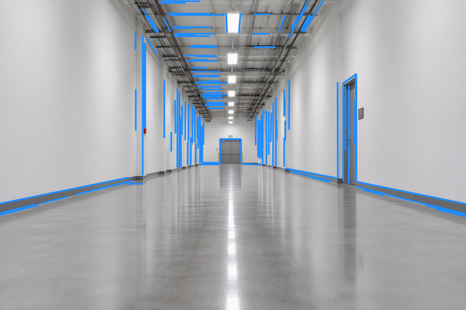
No single measurement source can overcome every case. Cameras constrain drift against the environment but depend on scene appearance. Encoders measure wheel motion on surfaces but accumulate errors and struggle when wheels slip. Inertial measurement units (IMUs) provide frequent motion updates, but small measurement errors accumulate over time and cause the position estimate to drift or lose precision.
The engineering problem is therefore not simply to add sensors. It is to integrate complementary measurements into the estimator, detect when individual measurements become unreliable, and preserve real-time execution on embedded hardware.
Adding Wheel Encoders Directly to cuVSLAM
The first ADI extension brings wheel measurements directly into cuVSLAM. Wheel encoders measure how far and in what direction a robot’s wheels move, giving the system another source of information alongside its cameras.
Rather than estimating movement separately from cameras and wheels and combining the results later, the enhanced system evaluates both sources together. This produces a more reliable estimate of the robot’s path and supports common mobile-robot designs, including differential-drive robots and car-like Ackermann-steered vehicles.
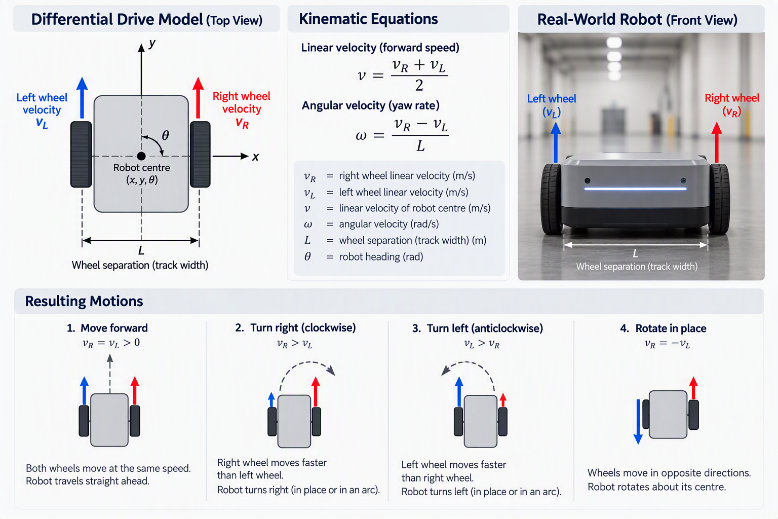
Testing with two high-resolution ADI TMCS-40 optical encoders showed a significant improvement. Across 13 ADI-AMR trajectory segments, the average position error fell from 24.2 to 9.7 centimeters when adding wheel measurements to vision. The worst error dropped from 1.923 meters to 0.275 meters, while runtime increased from 1.40 ms to 1.81 ms per frame on the evaluated NVIDIA Jetson platform.
Most importantly, the system’s prevented large errors during sharp, rotation-heavy movements. For deployed robots, avoiding these rare but serious failures can matter more than a modest improvement in average accuracy.
Handling Camera Blackout and Wheel Slip
Wheel encoders can help a robot maintain its position when camera images are unavailable, but wheel measurements are not always reliable. The enhanced system is therefore able to detect problems with either source, adjusting how it estimates the robot’s movement.
The team tested the enhancement by blocking the camera for five seconds in robots with and without a wheel encoder. Robots with a camera-encoder combination detected the loss of useful images and temporarily switched control to rely on wheel encoder data. The original algorithm in camera-only robots lost track of the robot. Robots sporting the combined system limited the position error to 13.2 centimeters until visual tracking resumed.
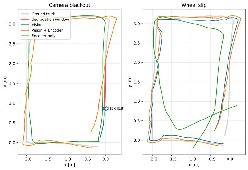
The opposite problem occurs when the wheels slip. In this situation, the encoders may report that the wheels are turning even though the robot is not moving as expected. The enhanced system compares wheel measurements with an independent camera-based estimate. If the two disagree significantly, the system reduces its reliance on the wheel data. During testing, wheel encoders alone produced an error of 1.106 meters, while the wheel and camera-enabled robots limited the error to 28.7 centimeters, close to the 24.9-centimeter result achieved with vision alone.
Together, these tests demonstrate an important design principle: wheel sensing should keep the robot localized when vision fails, while vision should prevent wheel slip from sending the robot off course. ADI’s tightly integrated approach achieves this by incorporating its extension directly into cuVSLAM’s position-estimation process.
Using Weak Geometry to Improve Tracking
Despite improving algorithm performance, wheel encoders lose accuracy due to wheel slip and accumulated measurement errors. As mentioned above, vision-only algorithms struggle in environments with large plain surfaces that offer too few distinct corners or textured points to track reliably. These environments often still contain persistent lines, such as the edges of door frames, shelves, floors, and walls.
The team’s second extension leveraged that fact to enable cuVSLAM to detect and track these lines alongside the existing visual points it was already tracking. Lines also provide additional information about the structure of the environment, helping the system estimate the robot’s movement when only a few reliable points remain visible.
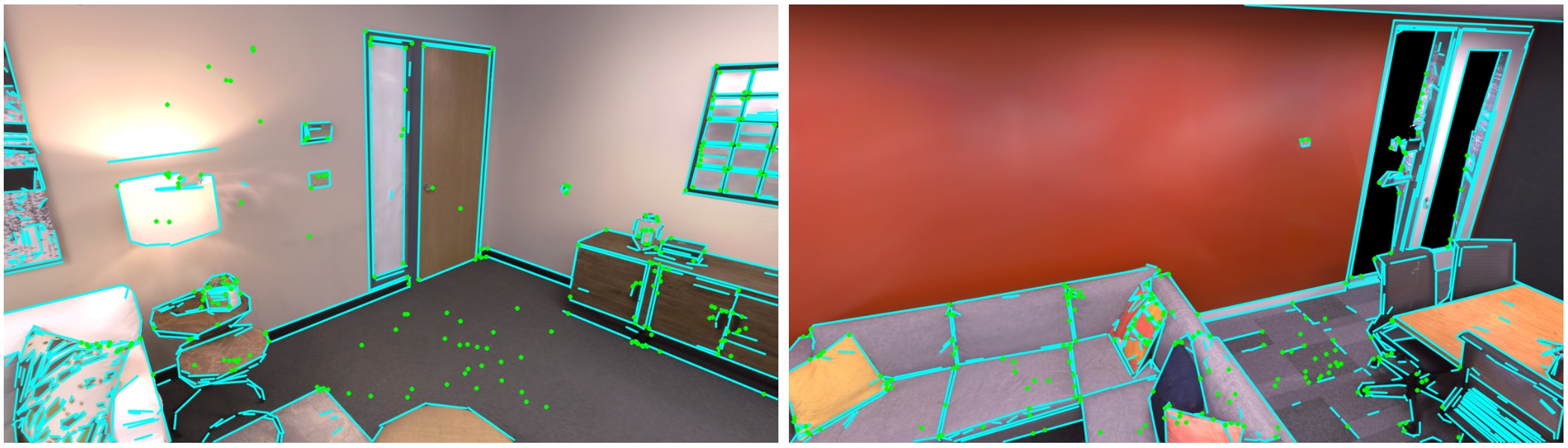
Yet tracking lines presents its own challenges. A line may appear shorter, longer, or partly hidden as the robot moves and the camera’s view changes. Repeating structures, such as rows of similar shelves, can also cause the system to match the wrong lines. To establish a line’s position accurately, the system generally needs to observe the line from multiple viewpoints.
Previous visual-inertial systems have demonstrated the value of combining points and lines. ADI’s work brings this approach into cuVSLAM and adds persistent line tracking, the fusion of observations from multiple viewpoints, adaptive balancing between points and lines, and GPU-accelerated processing within cuVSLAM’s existing position-estimation system.
Testing this approach using 30 indoor sequence datasets showed that position accuracy improved in 26 of the tests, and both ‘base’ point-tracking cuVSALM and the point-and-line configurations completed every sequence without losing track.
The greatest improvements appeared in structured environments with plain surfaces and few distinctive visual details. Performance declined slightly in some scenes containing nearby, repetitive structures, which could cause incorrect line matches. These results highlight an important lesson: tracking a smaller number of reliable lines is more valuable than tracking many uncertain ones. Future improvements could help the system identify unreliable line measurements and give them less influence.
Smart Fusion: Adaptive Balance Between Cameras and IMUs
The wheel-encoder and line-feature developments give cuVSLAM additional information. ADI’s third extension, Smart Fusion, takes a different approach: it continuously balances how much the system trusts the camera and the IMU based on current conditions.
Normally, cuVSLAM uses a fixed balance between camera observations and IMU measurements. It establishes that balance during calibration, but as we discussed - camera reliability can change as a robot moves and environments change.
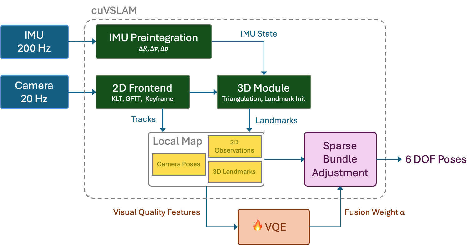
Smart Fusion evaluates the quality of the available visual information before each position update. It then selects one of two modes:
- VISION-TRUST: When visual features are plentiful, stable, and well-distributed it gives greater influence to camera observations.
- IMU-TRUST: When visual features are lost or camera-based estimates become less reliable, gives greater influence to IMU measurements.
A small machine-learning model makes this choice using ten indicators already collected by the tracker. These include the number and distribution of visible features, how long features remain visible, estimated depth, camera-tracking error, and the timing of IMU measurements. The model contains only 914 adjustable parameters, making it small enough to run before every position update.
This approach adjusts the overall balance between vision and the IMU. It works alongside cuVSLAM’s existing safeguards, which identify and reduce the influence of individual inaccurate measurements.
The team evaluated Smart Fusion against the EuRoC MAV and TUM-VI Room datasets using a testing method that kept each evaluation sequence separate from the data used to train the model.
Across all 11 EuRoC sequences, the average position error decreased from 20.2 centimeters to 14.6 centimeters, an improvement of 27.7%. Across five TUM-VI Room sequences, the average error decreased from 27.0 centimeters to 23.0 centimeters, an improvement of 14.9%.
Importantly, Smart Fusion does not replace cuVSLAM with a large, end-to-end AI model. Instead, it uses a compact machine-learning model to make one specific and understandable decision: whether the system should place more trust in its cameras or its IMU at a given moment.
Three Extensions, One System Strategy
The wheel-encoder, line-feature, and Smart Fusion projects respond to three different failure modes:
| ADI Extension | Primary Challenge | Solution |
| Wheel encoder fusion | Camera dropout, blur, weak visual tracking | Incorporate wheel-motion information |
| Weak geometry support | Too few visual details | Tracks structural edges and lines |
| Smart Fusion | Changing visual measurement quality | Ongoing visual-IMU weighting |
The value lies in the combination.
Wheel encoders supply short-term metric motion when camera observations weaken. Structural lines extract constraints from scenes where corner features are scarce. Smart Fusion changes estimator behavior as the quality of visual evidence varies. Each extension retains explicit geometric and sensor models, and each is designed to fit the existing cuVSLAM architecture rather than create a separate localization stack.
What This Enables for Robotics Engineers
ADI’s cuVSLAM extensions show the way towards a localization stack that successfully incorporates multiple sensing modalities without abandoning a validated visual estimator.
For system designers, the practical benefits are broad:
Enhanced robustness combining visual optimization and wheel encoder data – even when vision data is unavailable or wheels slip - even in low-texture environments. The GPU compatible extensions also incorporate and balance IMU data and offer common interfaces across wheeled platforms.
This is also a great example of system co-design: Sensors, estimation software, and compute should be developed as one system. Sensor quality determines the information available to the estimator. Estimator design determines how that information affects the trajectory. Compute architecture determines whether the complete pipeline can meet the robot’s latency and power constraints.
Next Steps
If you are interested in learning more details about ADI’s Extensions for cuVSLAM, you can read the complete scientific articles:
- Tightly Coupled Encoder Fusion for Robust cuVSLAM
- Line-Augmented cuVSLAM for Robust Low-Texture Visual Odometry, arxiv.org, 10/14/2026
- Smart Fusion for Adaptive Visual-IMU Weighting in cuVSLAM Sparse Bundle Adjustment, arxiv.org, 10/14/2026


